Schematics & Circuit Analysis
Circuit Details
This page collects circuit diagrams and technical details of the Ultimate 106's internal electronics. It will be added to over time as more of the unit is documented.
LED Indicator Circuit
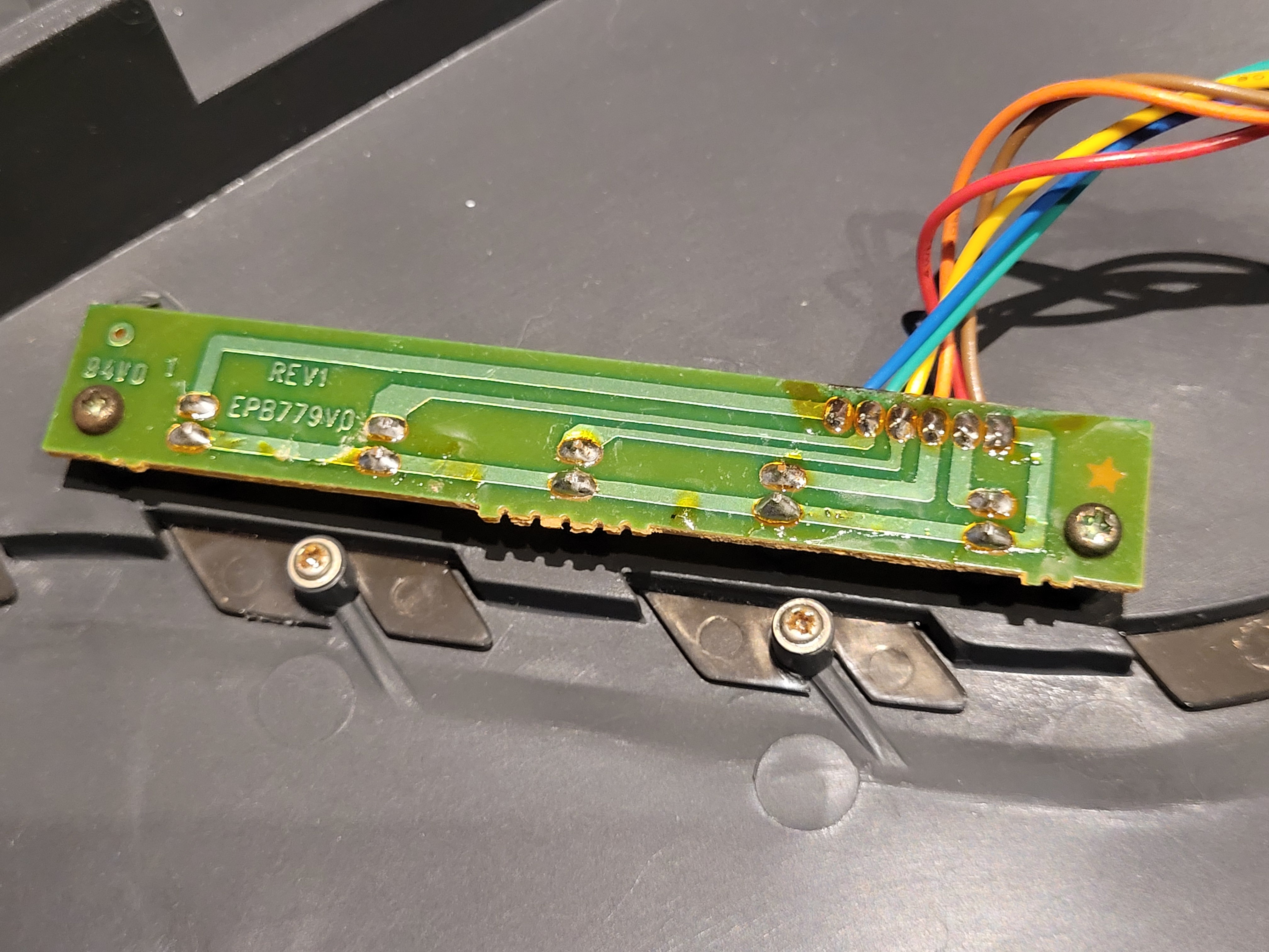
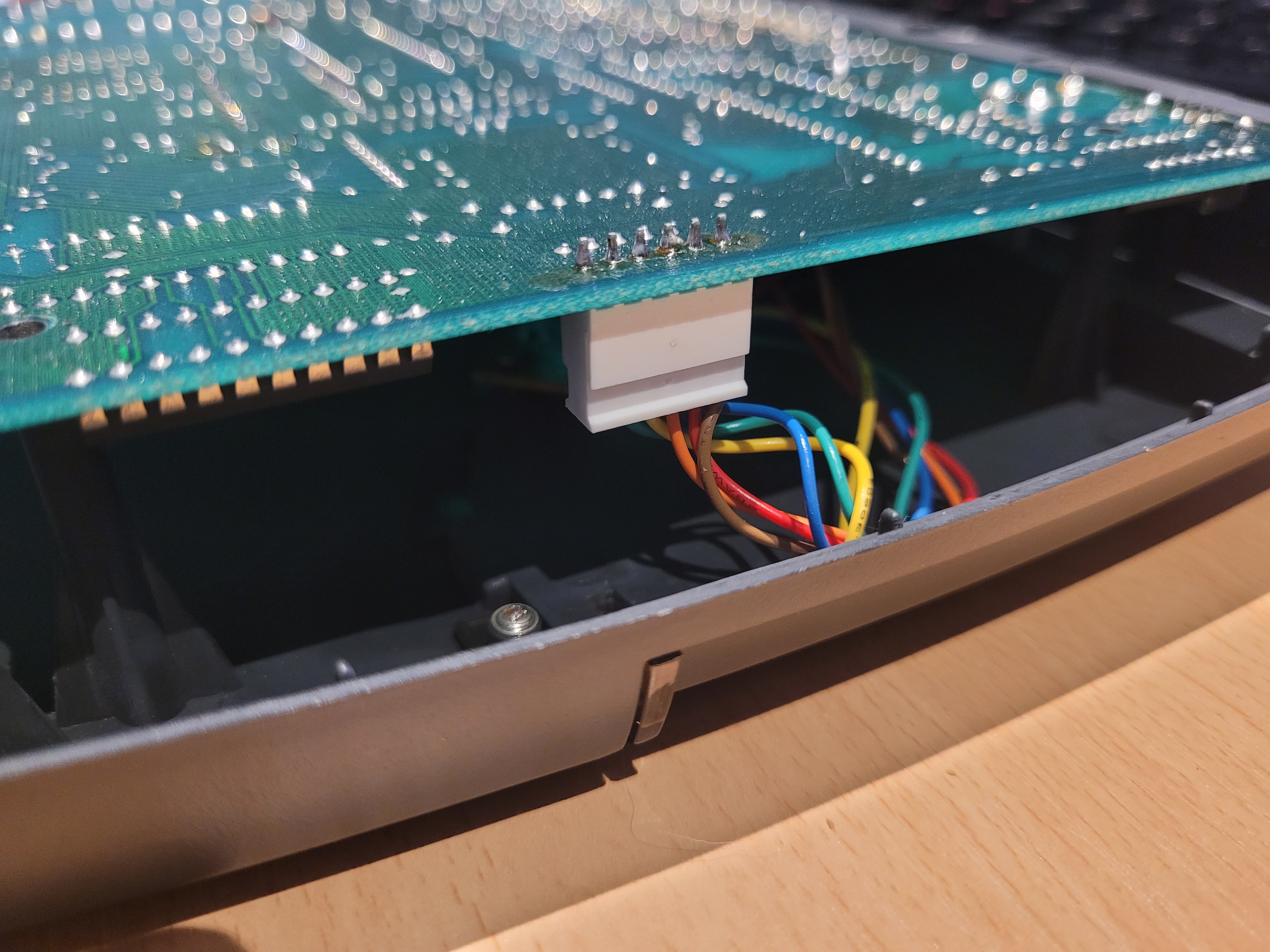
The five front-panel status LEDs are mounted on a small daughter board which connects to the main PCB via a multicore ribbon cable and a dedicated LED connector. Each LED is driven through a 470Ω current-limiting resistor, consistent with the same resistor value used elsewhere in the extension interface circuitry.
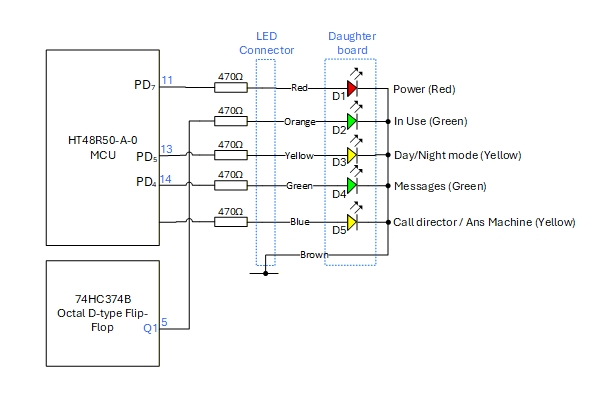
LED indicator circuit. Five LEDs (D1–D5) on a daughter board, each with a series 470Ω resistor. Four are driven directly from the HT48R50A-0 MCU port pins; the fifth via a 74HC374B octal D-type flip-flop.
LED assignments
| LED | Colour | Function | Driven by |
|---|---|---|---|
| D1 | Red | Power | MCU HT48R50A-0 — port PD₇ (pin 11) |
| D2 | Green | In Use | MCU HT48R50A-0 (pin 13 / PD₅ area) |
| D3 | Yellow | Day/Night Mode | MCU HT48R50A-0 — port PD₅ (pin 13) |
| D4 | Green | Messages | MCU HT48R50A-0 — port PD₄ (pin 14) |
| D5 | Yellow | Call Director / Answer Machine | 74HC374B octal D-type flip-flop — Q1 (pin 5) |
Notes
The use of a 74HC374B octal D-type flip-flop to drive D5 (Call Director/Answer Machine) is interesting — this suggests the state of that indicator is latched independently of the MCU's direct port outputs, likely so it can retain its state without the MCU continuously asserting the pin. The 74HC374 is an edge-triggered device, so the LED state is set on a clock edge and held until the next update.
The daughter board arrangement for the LEDs is a practical manufacturing choice — it allows the front panel assembly to be built and tested independently of the main PCB, and the LED positions to be set by the daughter board layout rather than requiring precision placement on the main board.
Physical hardware
The photographs below show the LED daughter board and its connector as they appear in the actual unit.