Ringing Circuit Failure
The Fault & The Fix
A relatively common fault with the Ultimate 106 is the failure of the ringing circuit, causing the extensions not to ring when dialled. The root cause is an age-related failure of two components in the high-voltage ringing generator: capacitor C22 and resistor R20.
The Ringing Generator Circuit
The ringing generator produces a high-voltage AC signal superimposed on a DC rail, which is distributed to each extension via an optoisolated triac (MOC3021). The MCU selects which extension to ring by gating individual triacs. The circuit topology uses a closed-loop regulated voltage source built around a TL084CN op-amp, a Darlington transistor pair (BF469 × 2), and a feedback network of resistors and capacitors.
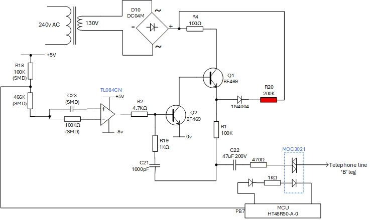
Ringing generator circuit schematic. R20 (highlighted in red) sits between the 1N4004 cathode and R4, forming part of the feedback loop. C22 is the smoothing capacitor on the regulated ringing voltage node.
How the circuit works
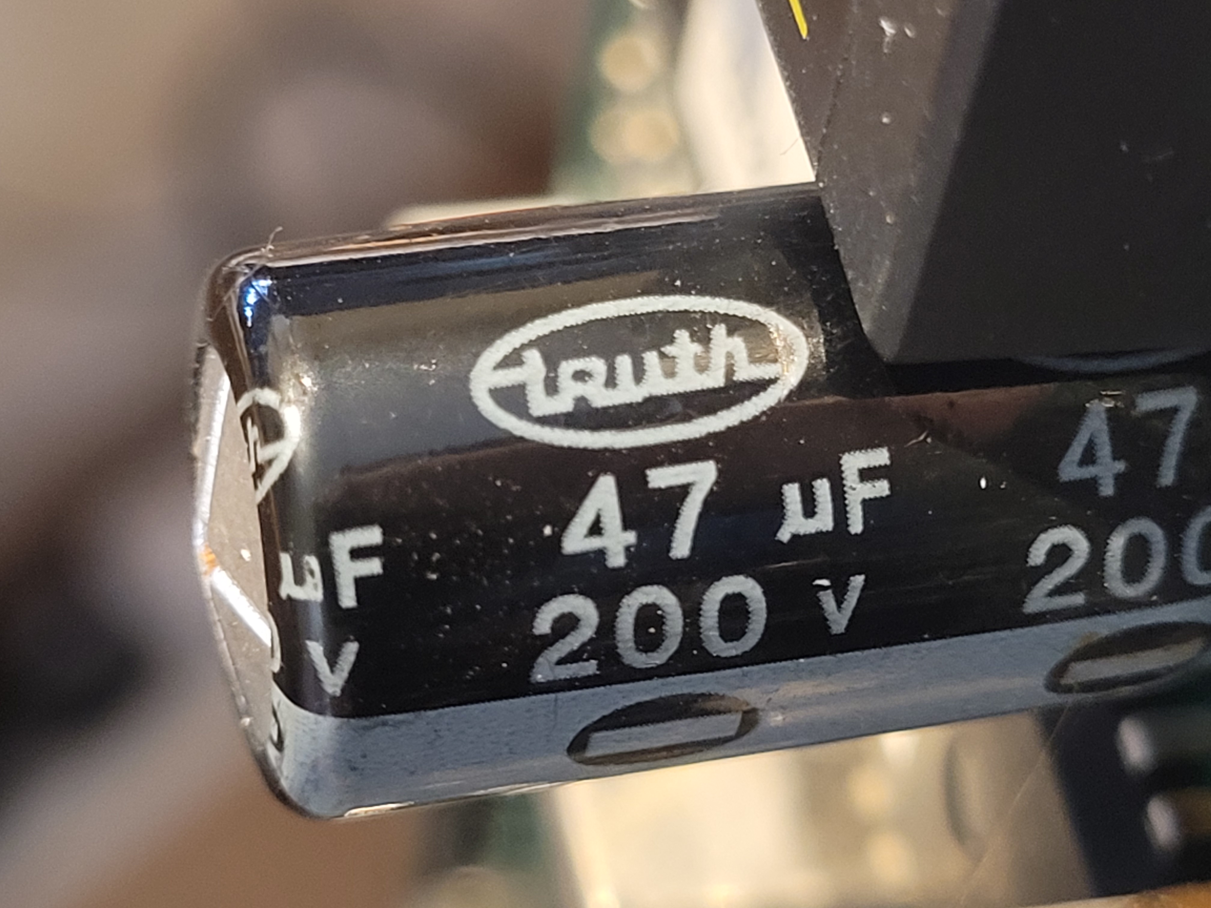
Q1 (BF469) operates as a common emitter stage with a large emitter resistor. The junction of R1 and C21/C22 forms the regulated ringing voltage node. C22 (47µF 200V) smooths the output, while C21 (1000pF) is the AC coupling and timing capacitor feeding back to the op-amp. Each extension is served by a MOC3021 optoisolator whose triac gate is driven from the C22 node via a 470Ω SMD resistor.
With R20 sitting between the 1N4004 cathode and R4, together with R1 and the Darlington pair, it forms a feedback loop creating a closed-loop controlled voltage source for the ringing signal.
The Failure Mode — A Cascade
The failure is not a random component failure but a predictable cascade driven by the age of the electrolytic capacitor C22.
Electrolytic capacitors of this age (mid-to-late 1990s manufacture) dry out over time, losing capacitance and — critically — exhibiting a rise in their ESR (Equivalent Series Resistance). The sequence of events is:
- C22 (47µF 200V electrolytic) ages, loses capacitance, and its ESR rises.
- Higher ESR causes more ripple current through C22, which in turn increases current on the supply rail.
- Increased rail current places greater stress on resistor R20.
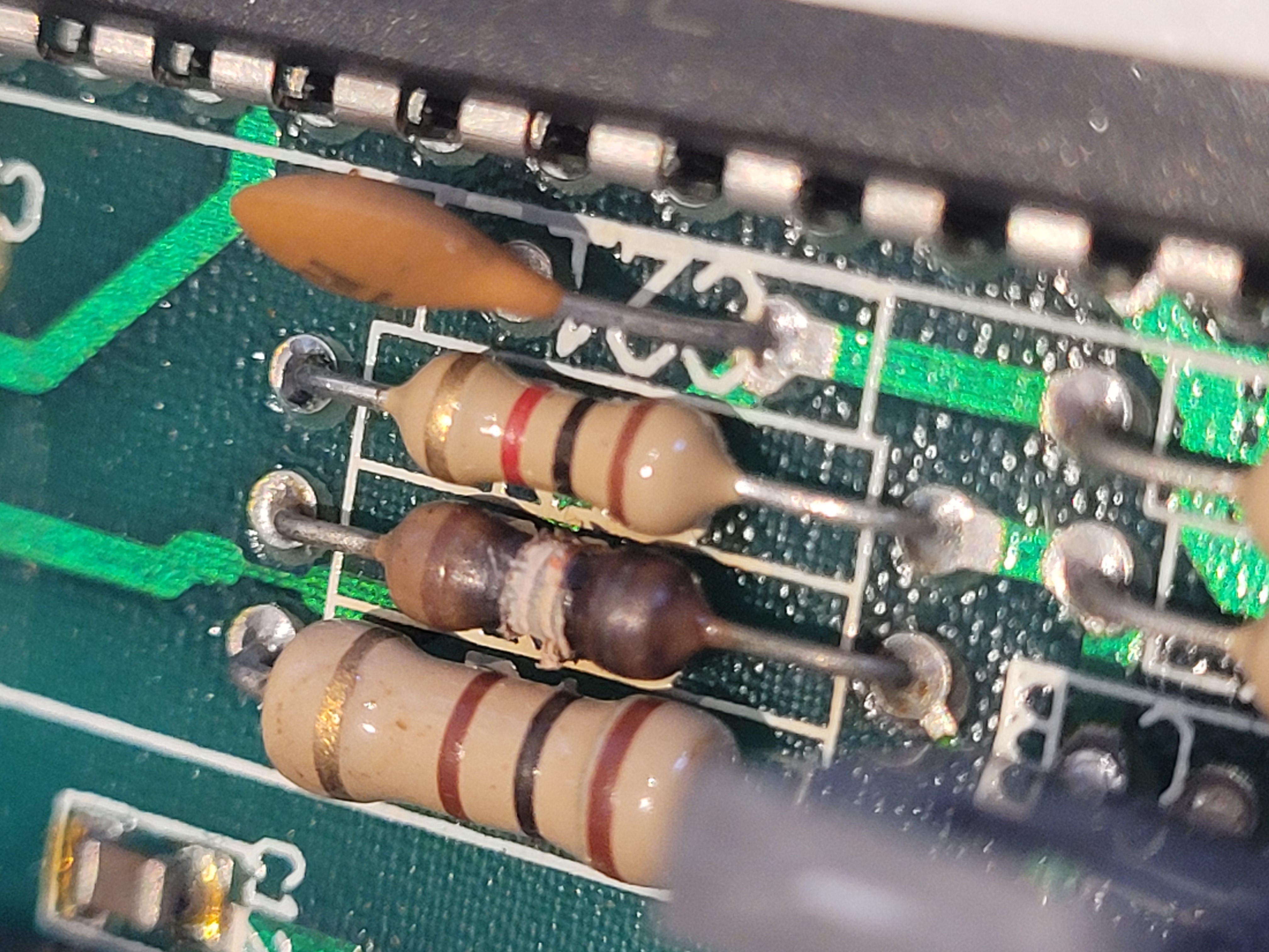
- R20 overheats and fails open circuit.
- With R20 open, there is no current limiting — the voltage across C22 rises uncontrolled.
- The uncontrolled voltage accelerates C22's failure completely.
In short: C22 probably started the cascade, and R20 was the victim. The characteristic "domed" appearance of C22 confirms the internal pressure build-up typical of a failing electrolytic.
Calculating the Replacement Value for R20
Because R20 had been so badly damaged that its colour bands were unreadable, its value had to be calculated from the circuit topology. The ratio of R1 to R20 determines the feedback fraction and thus the regulated output voltage at the C22 node.
R4: 100Ω
Q1 VCE(sat): ~1–2V
1N4004 forward drop: ~0.7V
R1: 100KΩ
Target output (C22 node): ~75V
Vout = Vsupply × (R1 / (R1 + R20))
75 = 183 × (100K / (100K + R20))
100K + R20 = 183 × 100K / 75
100K + R20 = 244K
R20 = 144KΩ → nearest standard value = 150KΩ
Power dissipation check
P = V² / R = 108² / 150,000 = 11,664 / 150,000
P ≈ 0.078W
This is comfortably within the rating of a standard ¼W resistor. However, given the history of thermal stress in this location, fitting a 1W or 2W rated resistor at 150KΩ would significantly improve long-term reliability. The unit documented here was repaired with a 200KΩ resistor as that was the closest available value to hand — this results in a slightly lower ringing voltage but the unit functioned correctly.
Summary — What to Replace
| Component | Value | Action |
|---|---|---|
| C22 | 47µF 200V electrolytic | Replace — look for the domed top as confirmation of failure |
| R20 | 150KΩ (calculated) — 200KΩ fitted as nearest available | Replace — heat damage will be visible; original value likely unreadable |
Sourcing a Replacement C22 — A Practical Note
Finding a direct like-for-like replacement for C22 is less straightforward than it might appear, due to changes in component dimensions over the past 25 years.
The original C22 is a radial electrolytic with a lead pitch of 7.5mm — the distance between the two pins. Modern 47µF 200V radial electrolytics are typically manufactured with a lead pitch of only 5mm. This means a modern direct-specification replacement will not sit flush with the PCB; the leads will need to be splayed outward to reach the 7.5mm hole spacing, leaving the capacitor standing proud of the board at an angle.
To obtain a 47µF capacitor with the correct 7.5mm lead pitch, it is necessary to step up to a 400V DC voltage rating. The higher voltage rating results in a larger physical body — approximately 16mm in diameter — compared to the 200V original. Whether a 16mm body fits comfortably in the available space on the PCB has not yet been confirmed; it is worth measuring the clearance in the ringing generator area before ordering.
Option 1 — 47µF 200V, 5mm pitch (modern standard part): Readily available, inexpensive. Leads must be splayed to fit the 7.5mm PCB footprint; capacitor will not sit flush. Electrically correct.
Option 2 — 47µF 400V, 7.5mm pitch: Correct lead pitch, sits flush on the PCB. Body diameter approximately 16mm — check clearance before fitting. Higher voltage rating is not a problem electrically and may offer a small margin of additional reliability.
Fuses — If the Unit Fails to Power Up
If the Ultimate 106 fails to power up at all — no LEDs, no response — before opening the case it is worth checking two fuses: one in the mains plug, and one on the PCB itself.
Mains plug fuse
The unit is rated at 45W. A 45W load on 230V draws approximately 200mA, meaning a 3A fuse is the correct rating for the mains plug. Units are sometimes found fitted with a 13A fuse — this is far too high for a 45W appliance and provides little protection in a fault condition. If your unit has a 13A fuse fitted, replace it with a 3A fuse as a matter of course.
Internal PCB fuse
The main PCB carries a 20mm fuse holder with a 250mA fuse fitted. This provides protection for the board's internal circuitry. If the unit has experienced a fault — such as the ringing circuit failure described above — it is possible this fuse has blown. Check it with a continuity tester or multimeter before assuming a more serious fault.
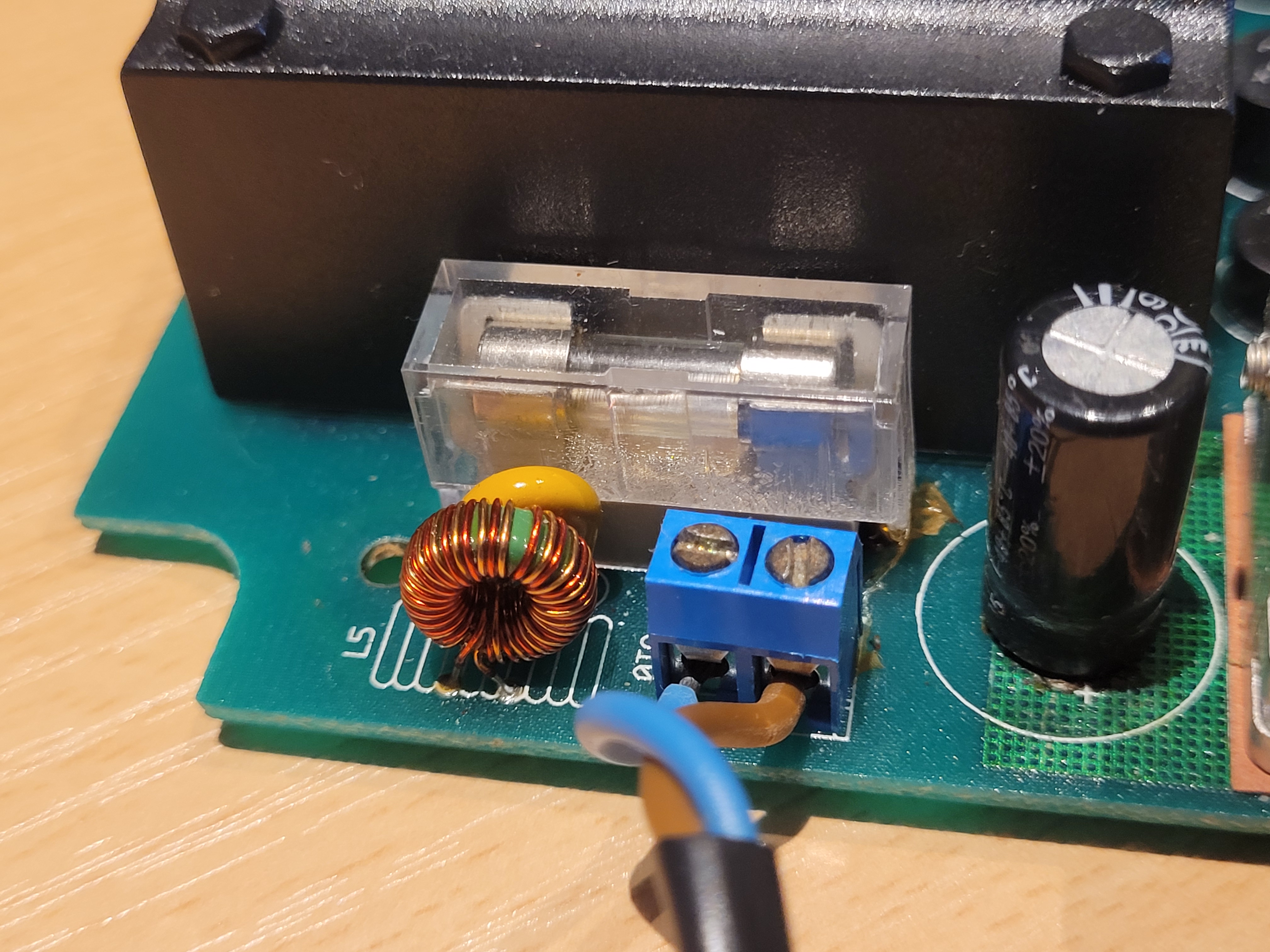
The 20mm fuse holder on the main PCB with the 250mA fuse clearly visible inside the transparent housing. Located in the power supply area of the board near the mains transformer.
| Fuse | Location | Correct Rating |
|---|---|---|
| Mains plug fuse | 13A plug fitted to mains lead | 3A |
| Internal PCB fuse | 20mm fuse holder on main PCB | 250mA |