Inside the Unit
Hardware Overview
The Ultimate 106 is housed in a compact dark grey desktop enclosure with a distinctive S-curve panel carrying the status LEDs. The top panel carries ventilation slots and the BT corporate logo. Despite its modest size, the internals are impressively comprehensive for a late-1990s small-business PABX.
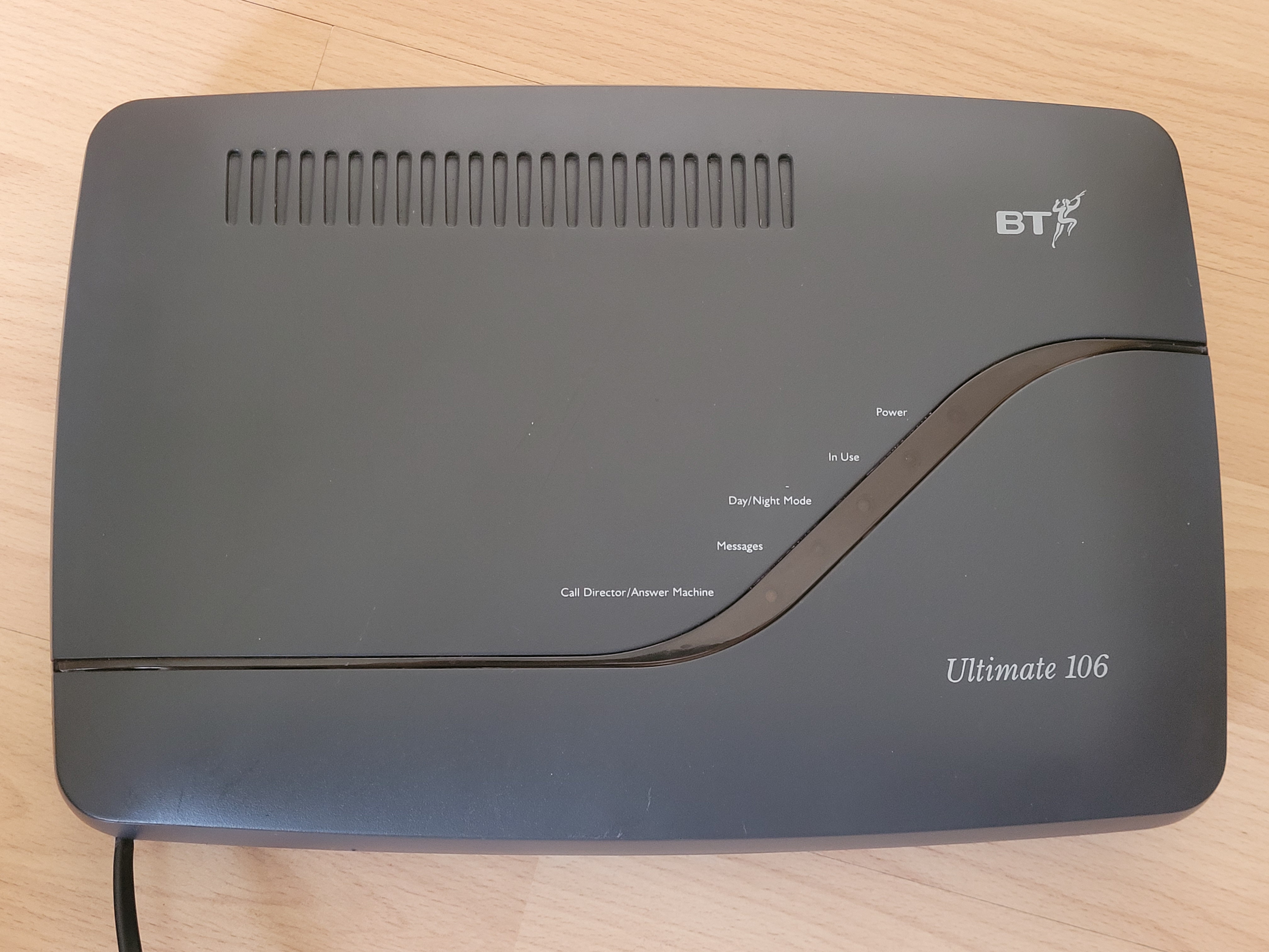
The BT Ultimate 106 — top view. Status indicators (left to right): Power, In Use, Day/Night Mode, Messages, Call Director/Answer Machine.
PCB Layout & Main Functions
The entire system is built on a single large PCB which occupies most of the enclosure. The board is clearly laid out with distinct functional areas, annotated in the photograph below. The PCB is marked ULTIMATE 106 REV9 PCB, copyright 1999 PDT Limited.
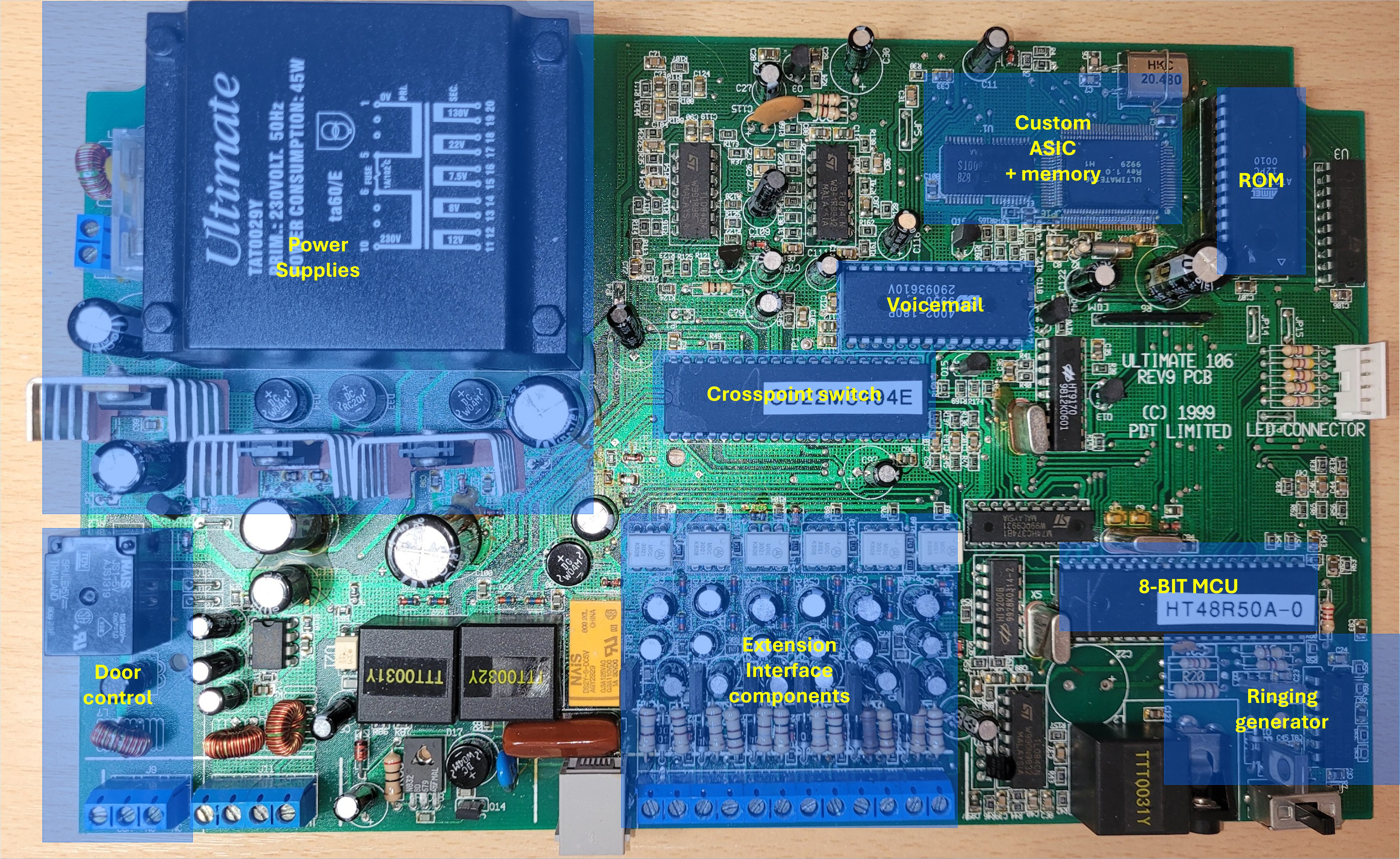
The Ultimate 106 main PCB with key functional areas highlighted. The board is a single assembly carrying all telephony, switching, and power functions.
Key Components
| Block | Description |
|---|---|
| Power Supplies | Mains transformer (TAT0029Y, 230V / 45W) with multiple secondary rails including 130V, 22V, 12V, 8V, 7.5V and a regulated +5V logic supply |
| Custom ASIC + Memory | Proprietary application-specific IC handling telephony functions, accompanied by supporting memory devices |
| ROM | System firmware ROM |
| Voicemail | Dedicated voicemail IC (Oki M29196E0) |
| Crosspoint Switch | Analogue crosspoint switching IC routing audio between extensions and external lines |
| 8-Bit MCU | HT48R50A-0 microcontroller — manages extension interface and ringing generation |
| Extension Interface | Per-extension line interface components including MOC3021 optoisolated triac drivers for ringing |
| Ringing Generator | High-voltage AC ringing signal generator — the subject of the fault documented on this site |
| Door Control | Relay-based door entry interface circuit |
Parts Database
A complete database of components used in the Ultimate 106 is available for reference. This covers all identifiable parts on the main PCB.