Reference Material
Further Notes
Original BT User Guide
A copy of the original BT Ultimate 106 User Guide is available to download below. This is the official documentation produced by BT for the product and covers installation, programming, and day-to-day operation of the system.
Disassembly Procedure
Access to the PCB requires careful disassembly of the enclosure. The process is straightforward but requires a Torx screwdriver as well as a standard Phillips head. Take care with the LED connector — it is the only step that requires a little finesse.
- Disconnect the unit from the mains supply and remove all telephone line and extension cables.
- Unclip the cable cover on the rear of the unit.
- Pop off the Programming button on the rear panel. The button simply clips on and can be lifted away using a small flat-bladed screwdriver or knife blade inserted gently under the edge. It will pop off cleanly. Do not attempt to separate the case halves without removing this button first — it will obstruct the cover and risks being broken.
- Remove the 2 black Phillips screws along the bottom edge of the case.
- Carefully turn the unit over and remove the 3 Torx screws along the top edge of the case.
- Carefully lift the front cover away slightly — do not pull it fully clear yet.
- Locate and disconnect the LED connector from the PCB. This allows the front cover to be fully removed. The connector is a small white push-fit plug — see the photograph on the Circuit Details page for reference.
- Remove the self-tapping screws securing the PCB to the rear case.
- Remove the mains cable clamp screws.
- The entire PCB assembly can now be lifted clear of the rear case.
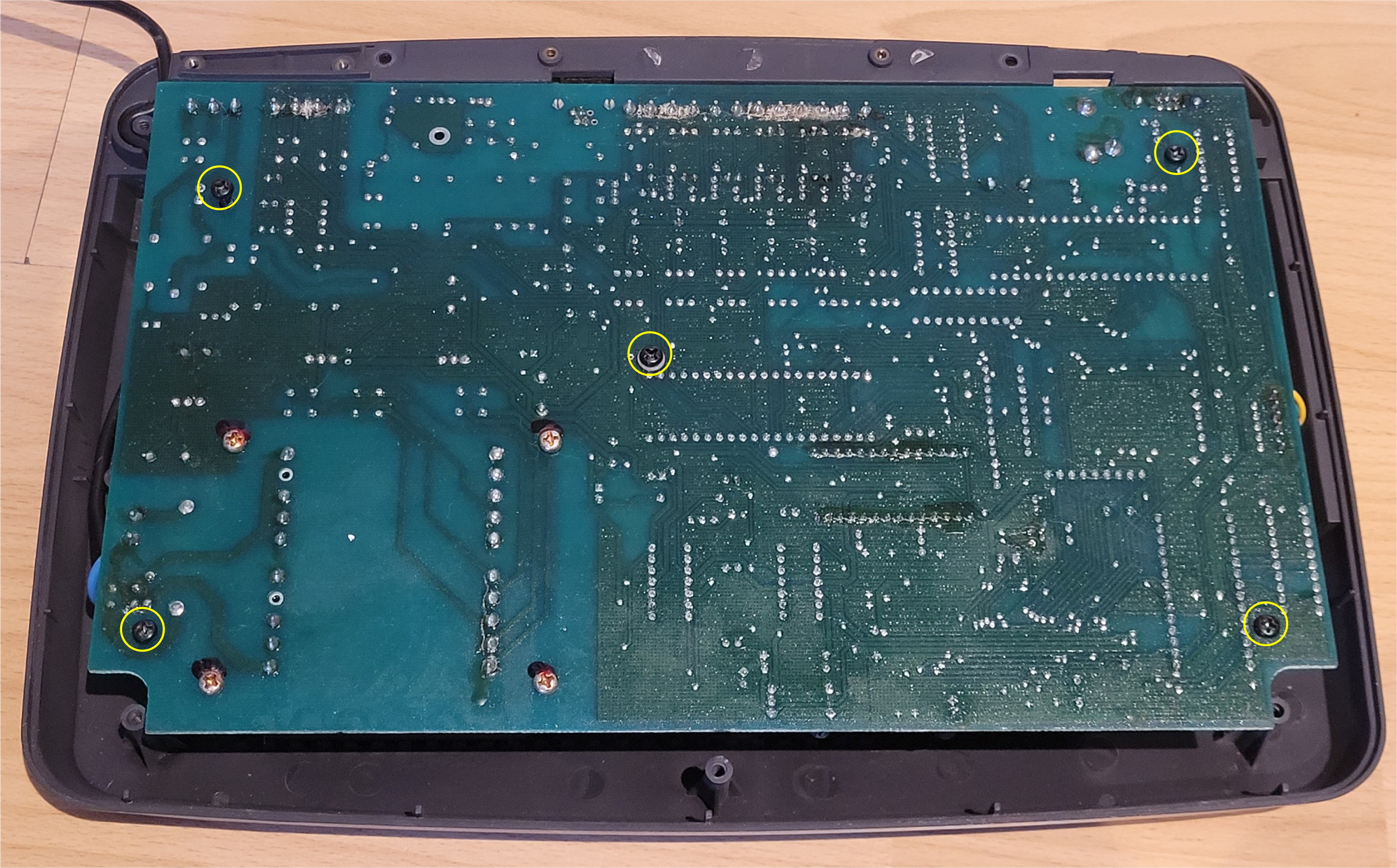
The solder side of the PCB with the rear case open. The five self-tapping screws securing the PCB to the case are highlighted in yellow circles — two along the top edge, one in the centre, and two along the bottom edge. Remove these (step 8) before lifting the PCB clear.
General Observations
Build quality
For a late-1990s small-business telephone system, the Ultimate 106 is well built. The PCB is clean, the layout logical, and the use of a single large board rather than interconnected sub-boards is sensible for reliability. The transformer is a robust toroidal-style unit rated at 45W, more than adequate for the load.
Age-related component risk
Units of this age (25+ years) should be treated with some caution regarding electrolytic capacitors throughout the board, not just in the ringing generator. If undertaking a repair, it is worth visually inspecting all electrolytics for signs of doming, leakage, or discolouration. The high-voltage capacitors in the power supply section deserve particular attention.
Extension ringing — MOC3021 triacs
Each extension is served by a MOC3021 optoisolated triac driver. These are reliable components but can be damaged if the ringing generator has been operating with uncontrolled voltage (as occurs when R20 fails open circuit). If, after replacing C22 and R20, individual extensions still fail to ring while others work correctly, a failed MOC3021 on the affected extension is a likely cause.
The HT48R50A-0 MCU
The 8-bit Holtek HT48R50A-0 microcontroller manages the extension interface and ringing selection. It gates the individual MOC3021 triacs to select which extension is rung. This is a simple, effective design — the MCU itself is unlikely to be a cause of ringing failure unless the ringing generator supply fault has caused a latch-up condition, which would be cleared by power cycling the unit.
If You Have the Same Fault
If you have arrived here because your Ultimate 106 powers up normally but extensions will not ring, the steps to resolve the fault are:
- Confirm the symptom — calls connect, voice works, but the telephone bell/ringer does not sound on any extension.
- Disassemble the unit following the procedure above.
- Locate the ringing generator area (bottom right of the PCB as oriented in the photograph on the Hardware page).
- Visually inspect C22 (47µF 200V) for a domed or bulged top — this will confirm the fault.
- Replace C22 with a new 47µF 200V electrolytic of the same or higher voltage rating.
- Inspect R20 for heat damage and discolouration. If damaged, replace with a 150KΩ resistor rated at 1W or 2W for improved longevity.
- Reassemble and test.
Extension Interface — Heat-Stressed Resistors
Each of the six extension ports has an identical line interface circuit, which includes a pair of resistors. When inspecting the board of the unit documented here, one resistor in the Extension 15 interface was found to be noticeably darker in colour than all of its counterparts — despite measuring the correct resistance of 180Ω on a cold DMM reading.
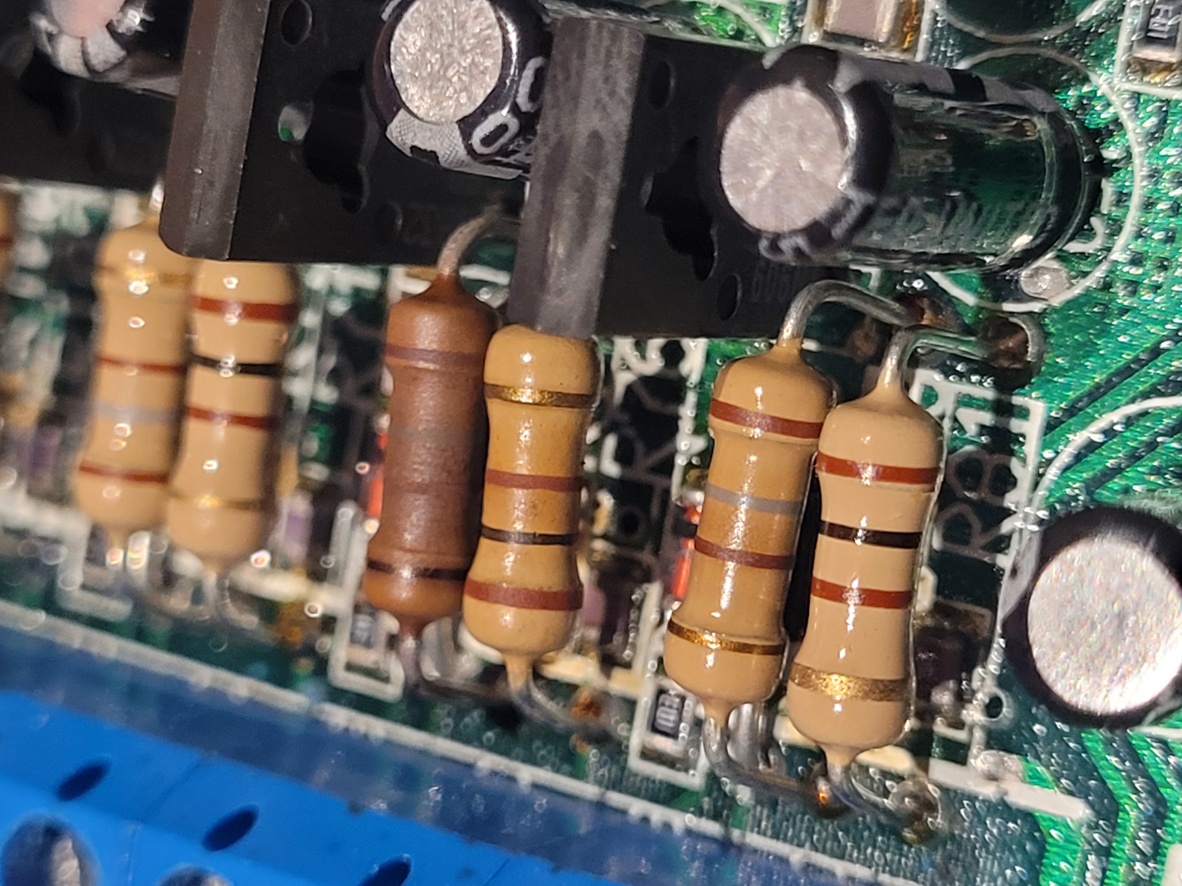
Extension interface resistors for Extensions 14, 15, and 16 (top to bottom). The 4th resistor from the bottom — part of the Extension 15 circuit — shows clear thermal discolouration compared to its neighbours, all of which measure 180Ω.
Does a correct resistance reading mean it's fine?
Not necessarily. Carbon film resistors that have experienced thermal stress can still measure at or near their nominal value when tested cold with a DMM, while having suffered internal degradation that affects their stability and behaviour under load or at operating temperature. A resistor that reads correctly at rest may drift under working conditions, particularly if it has already been running at the edge of its rated dissipation.
Why would one extension run hotter than the others?
Since all six extension interface circuits are identical, a resistor in one circuit running significantly hotter than its equivalents in the other five suggests something specific to that extension. Possible causes include:
- A telephone connected to that extension drawing more current than a modern electronic handset — old-fashioned bell-type telephones with electromagnetic ringers are a likely culprit, as they draw considerably more current than modern phones, particularly if permanently connected.
- A marginal component elsewhere in that extension's interface circuit causing the line to be loaded differently.
- A wiring fault or low-impedance condition on the extension cable itself.
- A slightly high-resistance solder joint on the resistor itself, generating additional heat at the joint.
In the unit documented here, all six extensions function correctly. The heat-stressed resistor has been replaced with a 1W rated equivalent — the same nominal resistance (180Ω) but with a much larger thermal margin, which should prevent any recurrence regardless of what caused the original stress. Replacing the matching resistor in the same extension's pair at the same time is also worthwhile.
Historical Note — BT Ultimate 106 Helpline
At the time the Ultimate 106 was in active service, BT operated a dedicated support helpline for the product on 0845 33 000 42. This number is no longer in use, as would be expected given the age of the product and the changes to BT's business over the intervening years.
The existence of a dedicated helpline reflects the scale of the Ultimate 106's deployment in small businesses across the UK during the late 1990s and early 2000s — it was clearly a widely-used product in its day, even if it has largely faded from awareness since.